
Before one can begin a discussion of soil nailing, a clear understanding of the difference between soil nails and tieback anchors is required. Many times one hears the term “Soil Nail” and “Tiebacks” used interchangeably and this can demonstrate a lack of understanding of the products.
Slab push piers work like any resistance end-bearing pier in that it does not rely on skin friction to produce support. Much like with any structure installation, the entire slab acts as the reaction force. The resistance slab pier is installed using a grid pattern. After installing the piers, the slab load is transferred across the piers uniformly and evenly by activating the hydraulic rams simultaneously.
One can easily understand that without some kind of containment of the soil at the face of the cut, a collapse of the soil along a failure plane is likely to occur. This failure can happen very quickly and without warning. The failure might look something like Figure 2. The unstable soil has moved to the bottom of the excavation leaving a natural and stable slope for the remaining soil. This interface between the stable and unstable soil is called a slip plane.
The most common way to prevent this kind of soil failure is to provide lateral support to the unstable soil situated in front of the slip plane. One common way to do this is with a retaining wall and tieback anchors. The tiebacks work together with the structural retaining wall to provide sufficient lateral support to retain the unstable soil mass. The retaining wall must be designed and constructed to provide rigid support for the soil mass across the distance between the tieback anchor placements. One often sees tieback anchors spaced eight to twelve feet or more apart along a retaining wall. The spacing and number of anchors depend upon the wall height, surcharge loads, and properties of the retained soil. Tieback anchors must be driven to a depth that is sufficient to provide tension resistance in the anchor shaft that is equal to the soil forces pushing against the retaining wall. A typical soil cut with a retaining wall is illustrated in Figure 3.
In many construction projects, soil nails are used to retain the unstable soil mass. To accomplish this, soil nails are installed in an evenly spaced close geometric pattern. When installing a soil nail stabilization project, the soil nail installations and the excavation must be accomplished in incremental depths of 4 to 6 feet until the final depth of cut is accomplished. Usually, only one increment can be completed per day. Immediately following the incremental excavation of the soil and the soil nail installations, the vertical face of the soil is covered with a steel-reinforced coating of shotcrete.
Soil nails are passive structural elements and are not tensioned after installation. The soil nail gains pullout resistance from within the sliding soil mass in front of the slip plane and the stable soil mass located behind the slip plane. The geometric system of soil nail placements creates an internally reinforced soil mass that is stable. Figure 4 shows a sketch of a typical soil nail installation.
Notice that each soil nail shaft has a great number of helical plates with the same diameter. These helical plates are evenly spaced along the entire length of the shaft. By comparison, a tieback anchor has one or more helical plates situated at the tip of the tieback. These helical plates generally increase in diameter along the shaft away from the tip. Once a tieback anchor lead section is installed, extensions without helical plates are used to extend the helical plates at the tip to the target depth. This characteristic of tieback anchors is clearly shown in Figure 3. On the other hand, soil nails will always have identical evenly spaced, small diameter helical plates along the entire shaft from beginning to end.
Soil nails may be the product of choice in applications where the vibrations from installing sheet piling or “H” piles may cause structural distress to nearby structures. Soil nails are generally installed to a shallower depth than tiebacks, which might be an advantage if deeply installed tiebacks have to cross property lines and/or terminate under structures owned by other parties; or be otherwise obstructed.
Soil nails work very efficiently in medium dense to dense sand with Standard Penetration Test values, “N” > 7 blows per foot. They also are suited for low plasticity cohesive soil (clays) with SPT values of “N” > 8 blows per foot, which also have soil cohesion values exceeding 1,000 psf through the entire depth of soil to be stabilized.
ECP Soil Nail Components
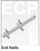
ECP Soil Nail products consist of a shaft fabricated from either 1-1/2 inch or 1-3/4 inch solid square steel bar. Welded along the entire length of the Soil Nail shaft are identically sized helical plates measuring six or eight inches in diameter with a plate thickness of 3/8 inch. The available lead shaft lengths for ECP Soil Nails are nominally five and seven feet long; however, other lengths may be specially fabricated. Soil nail extensions are also available in nominal lengths of five and seven feet long. The extensions also contain evenly spaced helical plates. Soil nail extensions are supplied with integral couplings and hardware for attachment to already installed lead or other extensions allowing the soil nail assembly to reach the designed length requirement.
Soil nails may be terminated with a large flat wall plate or an assembly of reinforcing bars welded to a small wall plate. These wall plates will eventually be embedded into the reinforced concrete wall covering.
Product Benefits
- Quickly Installed Using Rotary Hydraulic Torque Motor
- Installs With Little Or No Vibration
- Installs In Areas With Limited Access
- No Post-Tensioning – Immediate Support
- No Need for “H” Piles, Sheet Piling, or Walers
- Easily Load Tested To Verify Capacity
- In Temporary Applications, Soil Nail Removal and Reuse is Possible
Mechanics of ECP Soil Nail Installation
Soil nails not only look different from Torque Anchor™ tiebacks they are designed differently. It is important to understand the dramatic differences in these products before working with soil nails.
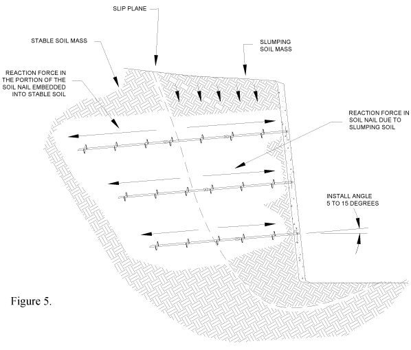
For soil nails to be effective, they must have helical plates of equal diameters spaced evenly along the entire length of the shaft. Remember that soil nails are not tensioned to gain strength; they gain pullout resistance from within the sliding soil mass that is located in front of the slip plane. The concept is rather simple to understand. As the soil mass begins to slip downward and outward, it pushes against the backside of the helical plates of the soil nail embedded within this sliding soil mass. The force generated by the sliding soil against these helical plates is resisted equally, and in the opposite direction, on the front side of the remaining helical plates on the Soil Nail shaft that is embedded within the stable soil behind the slip plane. Figure 5 illustrates the way that the forces are developed along the Soil Nail shaft.
The forces developed within the soil nail system reduce the structural requirements for the exterior wall. In most cases, the soil nails are connected directly to the wall without any need for sheet piles, “H” piles or wales. Because the soil mass is stabilized by the matrix of soil nails, only a thin shotcrete wall is necessary.
Soil nails are installed in a geometrical matrix to distribute the load more evenly; and as such, soil nails are more lightly loaded than tieback anchors. Some engineers might specify a small “seating” load be applied to the soil nail after installation to remove slack in the couplings; but in general, soil nails are usually not tensioned after installation as this can change the balance of stresses on the helices. Because soil nailing is a passive system, meaning that the soil nails are not post-tensioned, the unstable soil mass has to slump slightly before the soil nail system can develop forces to resist the soil movements.
Soil nailed walls are expected to deflect both downward and outward during the slumping of the soil mass with expected movements of approximately 1/8” of vertical and horizontal movement of the top of the wall for every five feet of excavation. These movements are normally not a concern except when an existing structure is situated near the top of the excavation. One way to relieve some of the overburden load from a nearby structure is to provide supplemental foundation support to the perimeter beam and/or column footings of the existing structure using ECP Steel Piers™. Transferring the structural load to the deep foundation piers not only reduces the surcharge on the soil mass but also prevents vertical settlement of the footing as the sliding soil mass moves during the tensioning of the soil nail matrix. If there are concerns with regard to lateral movements of the building’s footings, the designer has the ability to prevent lateral footing movements of the existing structure by using Torque Anchors™ along with ECP Steel Piers™ to provide both lateral and vertical stability.
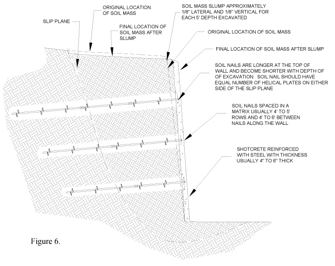
Figure 6 shows details of a typical soil nail installation. Usually, four to five feet of soil is excavated followed by the installation of the first row of soil nails. Notice that the first row has the longest shaft length because the distance to the slip plane is the greatest. The soil nail is not installed to a specified torsion requirement like with tieback anchors; rather the length of embedment, the installation angle and product spacing are the important elements in soil nail installations.
Once all of the soil nails situated within the first excavation increment are installed, one-half of the required thickness of shotcrete is placed on the wall followed immediately by the installation of the wall plates and reinforcing steel mesh. The reinforcing mesh is cut long enough to provide suitable splice overlap at the next increment of soil excavation. A surface coating of shotcrete is installed over the steel reinforcement to provide the specified final thickness. All work is then left to cure prior to the next excavated depth increment.
Prior to the beginning the next excavation increment (usually the next day), the amount of slump at the top of the excavation should be measured to insure that the wall is performing as intended. The next depth increment is then excavated followed by the installation of the next row of soil nails followed by the immediate installation of the first layer of shotcrete. The only difference between the initial and subsequent incremental excavations is that the new layers of shotcrete and steel must be interlocked to the previous work to provide continuity to the wall.
Shotcrete
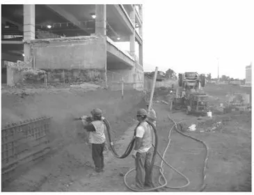
Shotcrete is a process where Portland cement concrete or mortar is propelled under air pressure onto a surface. We recommend the wet process where the dry ingredients are mixed with water and then sent to the spray nozzle as opposed to “Gunite” where the materials are mixed as they leave the nozzle. Shotcrete deposits are more concrete with less rebound upon impact than “Gunite”.
Engineering Design and Supervision
Design should involve professional geotechnical and engineering input. Each soil nail design requires very specific and detailed information involving the soil characteristics at the site and surcharge loads, if any. Each design is complicated and highly technical. The final design and specifications should only be prepared by a Registered Professional Engineer trained in soil nail design and familiar with the specific job and job site.
Field Documentation
It is very important for the installer to be aware that soil nailing projects involve risk and as such close communications with the engineer and attention to detail are extremely important. The data collected will assist the engineer to determine that the project is progressing according to plan. Field data should be recorded for each soil nail product installed. Usually, the field superintendent is the person responsible for recording field data. This raw field data is normally compiled at the end of the day into a Daily Installation Report. This report should be assembled in a form that is easy to read and understand. At the start of each day, the Daily Installation Report from the previous day should be provided to the engineer prior to beginning the next excavation increment. ECP suggests reporting the following data on each installed soil nail to the engineer each day:
- A diagram with the installed ECP Soil Nail locations numbered for reference
- ECP Soil Nail product part numbers of the items that were installed
- The elevation from the surface to the soil nail entry point
- The soil nail installation angle
- The installed length of the soil nail
- The installation torques required to advance the soil nail into the soil should be recorded at one-foot intervals
- Notes should be made, if needed, on the torsion log for each soil nail placement to report the presence of non-uniform soil or if the soil nail encounters an obstruction during installation